Human Spaceflights to the Moon
![]()
International Flight No. 41Apollo 15USA |
 |
 |
![]()
Launch, orbit and landing data
walkout photo |
 |
|||||||||||||||||||||||||||||||
alternative crew photo |
alternative crew photo |
|||||||||||||||||||||||||||||||
alternative crew photo |
alternative crew photo |
|||||||||||||||||||||||||||||||
alternative crew photo |
alternative crew photo |
|||||||||||||||||||||||||||||||
Crew
| No. | Surname | Given names | Position | Flight No. | Duration | Orbits | |
| 1 | Scott | David Randolph | CDR | 3 | 12d 07h 11m 52s | 1,5 | |
| 2 | Worden | Alfred Merrill | CMP | 1 | 12d 07h 11m 52s | 1,5 | |
| 3 | Irwin | James Benson "Jim" | LMP | 1 | 12d 07h 11m 52s | 1,5 |
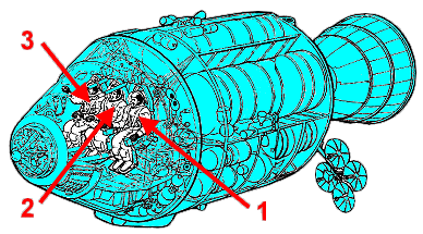
Crew seating arrangement
|
 |
|
||||||||||||||||
Backup Crew
|
 |
Support Crew
|
|||||||||||||
Hardware
| Launch vehicle: | Saturn V (SA-510) |
| Spacecraft: | Apollo (CSM-112 „Endeavour“ / LM-10 „Falcon“) |
Flight
|
Launch from Cape Canaveral (KSC) and
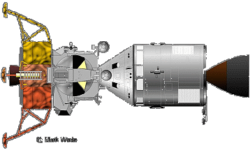
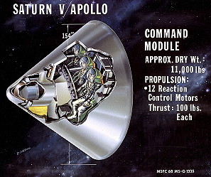
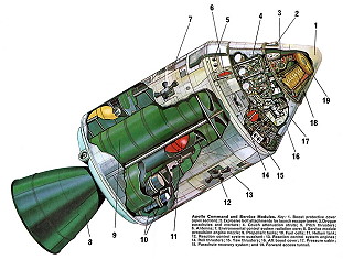
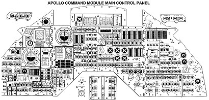
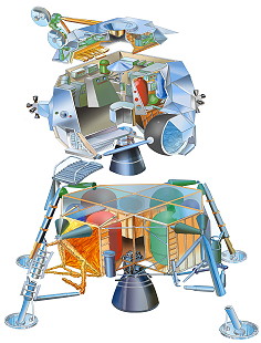
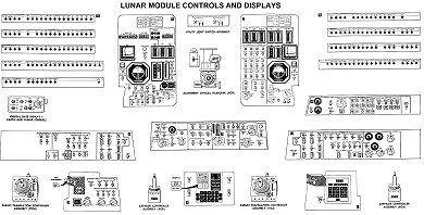
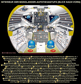
landing 500 km north of Hawaii in the Pacific Ocean. During the launch, the second stage of the Saturn V ignited when still close to the first stage, which could have caused a catastrophic event in which the exhaust of the first stage engine would have been forced back into the engine. Despite this, the rocket nominally reached an orbit around Earth a short time later. A couple of hours into the mission, the S-IVB third stage of the rocket reignited to propel the spacecraft out of Earth orbit and on to the Moon. The Command Module (CM) was a conical pressure vessel with a maximum diameter of 3.9 m at its base and a height of 3.65 m. It was made of an aluminum honeycomb sandwich bonded between sheet aluminum alloy. The base of the CM consisted of a heat shield made of brazed stainless steel honeycomb filled with a phenolic epoxy resin as an ablative material and varied in thickness from 1.8 to 6.9 cm. At the tip of the cone was a hatch and docking assembly designed to mate with the lunar module. The CM was divided into three compartments. The forward compartment in the nose of the cone held the three 25.4 m diameter main parachutes, two 5 m drogue parachutes, and pilot mortar chutes for Earth landing. The aft compartment was situated around the base of the CM and contained propellant tanks, reaction control engines, wiring, and plumbing. The crew compartment comprised most of the volume of the CM, approximately 6.17 cubic meters of space. Three astronaut couches were lined up facing forward in the center of the compartment. A large access hatch was situated above the center couch. A short access tunnel led to the docking hatch in the CM nose. The crew compartment held the controls, displays, navigation equipment and other systems used by the astronauts. The CM had five windows: one in the access hatch, one next to each astronaut in the two outer seats, and two forward-facing rendezvous windows. Five silver/zinc-oxide batteries provided power after the CM and SM detached, three for re-entry and after landing and two for vehicle separation and parachute deployment. The CM had twelve 420 N nitrogen tetroxide/hydrazine reaction control thrusters. The CM provided the re-entry capability at the end of the mission after separation from the Service Module. The Service Module (SM) was a cylinder 3.9 meters in diameter and 7.6 m long which was attached to the back of the CM. The outer skin of the SM was formed of 2.5 cm thick aluminum honeycomb panels. The interior was divided by milled aluminum radial beams into six sections around a central cylinder. At the back of the SM mounted in the central cylinder was a gimbal mounted re-startable hypergolic liquid propellant 91,000 N engine and cone shaped engine nozzle. Attitude control was provided by four identical banks of four 450 N reaction control thrusters each spaced 90 degrees apart around the forward part of the SM. The six sections of the SM held three 31-cell hydrogen oxygen fuel cells which provided 28 volts, two cryogenic oxygen and two cryogenic hydrogen tanks, four tanks for the main propulsion engine, two for fuel and two for oxidizer, and the subsystems the main propulsion unit. Two helium tanks were mounted in the central cylinder. Electrical power system radiators were at the top of the cylinder and environmental control radiator panels spaced around the bottom. The lunar module (LM) was a two-stage vehicle designed for space operations near and on the Moon. The spacecraft mass of 15,065 kg was the mass of the LM including astronauts, propellants and expendables. The dry mass of the ascent stage was 2180 kg and it held 2639 kg of propellant. The descent stage dry mass was 2034 kg and 8212 kg of propellant were onboard initially. The ascent and descent stages of the LM operated as a unit until staging, when the ascent stage functioned as a single spacecraft for rendezvous and docking with the command and service module (CSM). The descent stage comprised the lower part of the spacecraft and was an octagonal prism 4.2 meters across and 1.7 m thick. Four landing legs with round footpads were mounted on the sides of the descent stage and held the bottom of the stage 1.5 m above the surface. The distance between the ends of the footpads on opposite landing legs was 9.4 m. One of the legs had a small astronaut egress platform and ladder. A one meter long conical descent engine skirt protruded from the bottom of the stage. The descent stage contained the landing rocket, two tanks of aerozine 50 fuel, two tanks of nitrogen tetroxide oxidizer, water, oxygen and helium tanks and storage space for the lunar equipment and experiments, and in the case of Apollo 15, 16, and 17, the lunar rover. The descent stage served as a platform for launching the ascent stage and was left behind on the Moon. The ascent stage was an irregularly shaped unit approximately 2.8 m high and 4.0 by 4.3 meters in width mounted on top of the descent stage. The ascent stage housed the astronauts in a pressurized crew compartment with a volume of 6.65 cubic meters which functioned as the base of operations for lunar operations. There was an ingress-egress hatch in one side and a docking hatch for connecting to the CSM on top. Also mounted along the top were a parabolic rendezvous radar antenna, a steerable parabolic S-band antenna, and 2 in-flight VHF antennas. Two triangular windows were above and to either side of the egress hatch and four thrust chamber assemblies were mounted around the sides. At the base of the assembly was the ascent engine. The stage also contained an aerozine 50 fuel and an oxidizer tank, and helium, liquid oxygen, gaseous oxygen, and reaction control fuel tanks. There were no seats in the LM. A control console was mounted in the front of the crew compartment above the ingress-egress hatch and between the windows and two more control panels mounted on the side walls. The ascent stage was launched from the Moon at the end of lunar surface operations and returned the astronauts to the CSM. The descent engine was a deep-throttling ablative rocket with a maximum thrust of about 45,000 N mounted on a gimbal ring in the center of the descent stage. The ascent engine was a fixed, constant-thrust rocket with a thrust of about 15,000 N. Maneuvering was achieved via the reaction control system, which consisted of the four thrust modules, each one composed of four 450 N thrust chambers and nozzles pointing in different directions. Telemetry, TV, voice, and range communications with Earth were all via the S-band antenna. VHF was used for communications between the astronauts and the LM, and the LM and orbiting CSM. There were redundant transceivers and equipment for both S-band and VHF. An environmental control system recycled oxygen and maintained temperature in the electronics and cabin. Power was provided by 6 silver-zinc batteries. Guidance and navigation control were provided by a radar ranging system, an inertial measurement unit consisting of gyroscopes and accelerometers, and the Apollo guidance computer. The Apollo Lunar Surface Experiments Package (ALSEP) consisted of a set of scientific instruments emplaced at the landing site by the astronauts. The instruments were arrayed around a central station which supplied power to run the instruments and communications so data collected by the experiments could be relayed to Earth. The central station was a 25 kg box with a stowed volume of 34,800 cubic cm. Thermal control was achieved by passive elements (insulation, reflectors, thermal coatings) as well as power dissipation resistors and heaters. Communications with Earth were achieved through a 58 cm long, 3.8 cm diameter modified axial-helical antenna mounted on top of the central station and pointed towards Earth by the astronauts. Transmitters, receivers, data processors and multiplexers were housed within the central station. Data collected from the instruments were converted into a telemetry format and transmitted to Earth. The ALSEP system and instruments were controlled by commands from Earth. The SNAP-27 model RTG produced the power to run the ALSEP operations. The generator consisted of a 46 cm high central cylinder and eight radiating rectangular fins with a total tip-to-tip diameter of 40 cm. The central cylinder had a thinner concentric inner cylinder inside, and the two cylinders were attached along their surfaces by 442 spring-loaded lead-telluride thermoelectric couples mounted radially along the length of the cylinders. The generator assembly had a total mass of 17 kg. The power source was an approximately 4 kg fuel capsule in the shape of a long rod which contained plutonium-238 and was placed in the inner cylinder of the RTG by the astronauts on deployment. Plutonium-238 decays with a half-life of 89.6 years and produces heat. This heat would conduct from the inner cylinder to the outer via the thermocouples which would convert the heat directly to electrical power. Excess heat on the outer cylinder would be radiated to space by the fins. The RTG produced approximately 70 W DC at 16 V. (63.5 W after one year.) The electricity was routed through a cable to a power conditioning unit and a power distribution unit in the central station to supply the correct voltage and power to each instrument. The Lunar Roving Vehicle (LRV) was an electric vehicle designed to operate in the low-gravity vacuum of the Moon and to be capable of traversing the lunar surface, allowing the Apollo astronauts to extend the range of their surface extravehicular activities. Three LRVs were driven on the Moon, one on Apollo 15 by astronauts David Scott and James Irwin, one on Apollo 16 by John Young and Charles Duke, and one on Apollo 17 by Eugene Cernan and Harrison Schmitt. Each rover was used on three traverses, one per day over the three-day course of each mission. On Apollo 15 the LRV was driven a total of 27.8 km in 3 hours, 2 minutes of driving time. The longest single traverse was 12.5 km and the maximum range from the LM was 5.0 km. On Apollo 16 the vehicle traversed 26.7 km in 3 hours 26 minutes of driving. The longest traverse was 11.6 km and the LRV reached a distance of 4.5 km from the LM. On Apollo 17 the rover went 35.9 km in 4 hours 26 minutes total drive time. The longest traverse was 20.1 km and the greatest range from the LM was 7.6 km. The Lunar Roving Vehicle had a mass of 210 kg and was designed to hold a payload of an additional 490 kg on the lunar surface. The frame was 3.1 meters long with a wheelbase of 2.3 meters. The maximum height was 1.14 meters. The frame was made of aluminum alloy 2219 tubing welded assemblies and consisted of a 3-part chassis which was hinged in the center so it could be folded up and hung in the Lunar Module quad 1 bay. It had two side-by-side foldable seats made of tubular aluminum with nylon webbing and aluminum floor panels. An armrest was mounted between the seats, and each seat had adjustable footrests and a velcro seatbelt. A large mesh dish antenna was mounted on a mast on the front center of the rover. The suspension consisted of a double horizontal wishbone with upper and lower torsion bars and a damper unit between the chassis and upper wishbone. Fully loaded the LRV had a ground clearance of 36 cm. The wheels consisted of a spun aluminum hub and an 81.8 cm diameter, 23 cm wide tire made of zinc coated woven 0.083 cm diameter steel strands attached to the rim and discs of formed aluminum. Titanium chevrons covered 50% of the contact area to provide traction. Inside the tire was a 64.8 cm diameter bump stop frame to protect the hub. Dust guards were mounted above the wheels. Each wheel had its own electric drive, a DC series wound 0.25 hp motor capable of 10,000 rpm, attached to the wheel via an 80:1 harmonic drive, and a mechanical brake unit. Maneuvering capability was provided through the use of front and rear steering motors. Each series wound DC steering motor was capable of 0.1 hp. Both sets of wheels would turn in opposite directions, giving a steering radius of 3.1 meters, or could be decoupled so only one set would be used for steering. Power was provided by two 36-volt silver-zinc potassium hydroxide non-rechargeable batteries with a capacity of 121 amp-hr. These were used to power the drive and steering motors and also a 36-volt utility outlet mounted on front of the LRV to power the communications relay unit or the TV camera. Passive thermal controls kept the batteries within an optimal temperature range. A T-shaped hand controller situated between the two seats controlled the four drive motors, two steering motors and brakes. Moving the stick forward powered the LRV forward, left and right turned the vehicle left or right, pulling backwards activated the brakes. Activating a switch on the handle before pulling back would put the LRV into reverse. Pulling the handle all the way back activated a parking brake. The control and display modules were situated in front of the handle and gave information on the speed, heading, pitch, and power and temperature levels. Navigation was based on continuously recording direction and distance through use of a directional gyro and odometer and inputting this data to a computer which would keep track of the overall direction and distance back to the LM. There was also a Sun-shadow device which could give a manual heading based on the direction of the Sun, using the fact that the Sun moved very slowly in the sky. The image at left shows a diagram of the layout of the control and display module, the Sun-shadow device is at top center between the heading and speed readouts. Deployment of the LRV from the LM quad 1 by the astronauts was achieved with a system of pulleys and braked reels using ropes and cloth tapes. The rover was folded and stored in quad 1 with the underside of the chassis facing out. One astronaut would climb the egress ladder on the LM and release the rover, which would then be slowly tilted out by the second astronaut on the ground through the use of reels and tapes. As the rover was let down from the bay most of the deployment was automatic. The rear wheels folded out and locked in place and when they touched the ground the front of the rover could be unfolded, the wheels deployed, and the entire frame let down to the surface by pulleys. The rover components locked into place upon opening. Cabling, pins, and tripods would then be removed and the seats and footrests raised. After switching on all the electronics, the vehicle was ready to back away from the LM. The image at right shows an earlier version of the planned deployment which does not exactly match the final sequence, note for example that the rover is facing away from the LM after deployment. The Apollo 15 subsatellite (PFS-1) was a small satellite released into lunar orbit from the Apollo 15 Service Module. Its main objectives were to study the plasma, particle, and magnetic field environment of the Moon and map the lunar gravity field. Specifically, it measured plasma and energetic particle intensities and vector magnetic fields, and facilitated tracking of the satellite velocity to high precision. A basic requirement was that the satellite acquire fields and particle data everywhere on the orbit around the Moon. A virtually identical subsatellite was also deployed by Apollo 16. The Moon's roughly circular orbit about the Earth at ~380000 km (60 Earth radii) carried the subsatellite into both interplanetary space and various regions of the Earth's magnetosphere. The satellite orbited the Moon and returned data from August 04, 1971 until January 1973. The Apollo 15 subsatellite was a hexagonal cylinder 78 cm in length and approximately 36 cm across opposite corners of the hexagon with a mass of 36.3 kg. Three equally-spaced 1.5-meter-long deployable booms were hinged to one of the end platforms. A fluxgate magnetometer was on the end of one boom and the other two carried tip masses to provide balance. A short cylinder was attached to the end platform opposite the booms and was used for the initial deployment and spin-up of the satellite, which was achieved using a spring-loaded mechanism in the SM bay. A wobble damper inside the satellite removed precessional and nutational motions. An S-band antenna protruded from the panel opposite the booms. Solar panels covering the six sides provided about 24 W of energy in sunlight and an average power of 14 W over one orbit of the Moon. The power subsystem also included a battery pack of 11 silver cadmium cells. An S-band transmitter was capable of sending 128 bits/s to the Earth. A magnetic core memory unit provided a storage capacity of 49,152 bits when the spacecraft could not transmit directly. Two solid state particle telescopes were mounted on an end panel of the spacecraft and four particle analyzer devices were attached to the sides. Apollo 15 launched on July 26, 1971 at 13:34:00 UTC on Saturn V SA-510 from Pad 39-A at Kennedy Space Center. The spacecraft was inserted into Earth orbit at 13:45:44 UTC and translunar injection took place at 16:30:03 UTC. The CSM separated from the S-IVB stage at 16:56:24 UTC and docked with the LM at 17:07:49 UTC. The S-IVB stage was released and burns at 19:22 UTC and 23:34 UTC sent the stage into a lunar impact trajectory. (It impacted the lunar surface on July 29, 1971 at 20:58:42.9 UTC at 1.51 S, 11.81 W with a velocity of 2.58 km/s at a 62-degree angle from the horizontal.) A short was discovered in the service propulsion system and contingency procedures were developed for using the engine. A mid-course correction was performed on July 27, 1971 at 18:14:22 UTC and another on July 29, 1971 at 15:05:15 UTC. During cruise it was discovered that the LM range/range-rate exterior glass cover had broken and a small water leak had developed in the CM requiring repair and clean-up. The SIM door was jettisoned at 15:40 UTC and lunar orbit insertion took place at 20:05:47 UTC. The descent orbit maneuver was executed at 00:13:49 UTC on July 30, 1971. A few days after launching from Florida, the spacecraft passed behind the far side of the Moon, where the Service Propulsion System engine on the Apollo Command/Service Module ignited for a six-minute burn to slow the craft down into an initial lunar orbit. Once the lowest point of altitude was reached in the orbit, the SPS engine was fired again to further stabilize the orbit of the Apollo CSM/Apollo Lunar Module stack and prepare for landing at Hadley. The majority of the first part of the day after arriving in lunar orbit, July 30, 1971, was spent preparing the Lunar Module for the descent to the lunar surface later on that day. After preparations were complete, un-docking from the CSM was attempted, but did not occur because of the faulty seal in the hatch mechanism. Command Module Pilot Alfred Worden re-sealed the hatch and the LM then successfully separated from the CSM. David Scott and James Irwin continued preparations for the descent while Alfred Worden remained in the CSM, returning to a higher orbit to perform lunar observations and await their return a few days later. Soon thereafter, David Scott and James Irwin began the descent to the Hadley landing site on the surface. Several minutes after descent was initiated, at pitch-over and the beginning of the approach phase of the landing, the LM was six kilometers east of the pre-selected landing target. Upon learning of this, David Scott altered the flight path of the LM and touched down at 22:16:29 UTC on July 30, 1971 at Hadley, within a few hundred meters of the planned landing site. While previous crews had exited the Lunar Module shortly after landing, the crew of Apollo 15 would be spending a substantially longer amount of time on the surface than previous crews. In order to preserve their sleep rhythm, the crew elected to spend the rest of the day inside the LM and wait until the next day to perform the first of three Extra-vehicular activities (EVAs), or moonwalks. Before beginning their sleep period, a SEVA (0h 33m) was partly a response to the surface navigation problems experienced on Apollo 14. David Scott stood atop Falcon's ascent engine cover with his shoulders through the top hatch so he could get his bearings at the complex Hadley-Apennine landing site ahead of the surface EVAs. He told Edgar Mitchell in Mission Control that the site was "exactly like what you had on Apollo 14. It's very hummocky, and, as you know, in this kind of terrain you can hardly see over your eyebrows." David Scott reported that 5000-m (16,500-ft) Mt. Hadley glowed gold and brown in the lunar morning sunlight, and that there were no large boulders to hinder the progress of the Lunar Roving Vehicle (LRV) during the next day's scheduled traverse south to St. George Crater. The mission was the fourth moon landing in space history. The landing site was the Hadley Apennine region near Apennine Mountains. Lunar surface stay-time was 66h 55m. Three EVAs were performed by David Scott and James Irwin. The first EVA occurred on July 31, 1971 (6h 32m). After unloading the Lunar Roving Vehicle (LRV), the two droves to the first moonwalk's primary destination, Elbow Crater, along the edge of Hadley Rille. James Irwin took the first of several harmless Apollo 15 falls during LRV deployment. The astronauts found that the rover had no front-wheel steering, but David Scott was able to maneuver the vehicle using only rear steering. They also found that their seatbelts barely fit around their pressurized EMUs. About 3 hours into the EVA David Scott and James Irwin set out on a 10.3-km (6.2-mi) traverse south along the rim of Elbow Crater to 2.25-km-dia (1.4-mi-dia) St. George Crater, near Hadley Rille. During the traverse the astronauts reduced suit cooling to avoid becoming cold while their metabolic rates were low. They had some difficulty with "zero phase lighting" (light reflected from the landscape opposite the Sun) which made obstacles difficult to discern. The astronauts used a rake to collect "walnut-sized samples" near St. George Crater. Flight controllers in Houston operated the LRV camera so geologists on Earth could explore the lunar landscape telerobotically and guide the astronauts in collecting samples. On returning to the LM Falcon, David Scott and James Irwin deployed the Apollo Lunar Surface Experiments Package (ALSEP). They located the central station 110 m (335 ft) west of the LM and drilled a hole in the ground for the heatflow experiment probe. David Scott used more oxygen than expected, so flight controllers terminated the EVA 30 minutes early and considered cutting back the second EVA. The second EVA was performed on August 01, 1971 (7h 12m). The target of the second EVA was the edge of Mount Hadley Delta, where the pair sampled boulders and craters along the Apennine Front. They began a 12.5-km (7.5-mi) traverse southeast to the foot of the Hadley Delta mountain and back, passing Index, Arbeit, Crescent, Spur, and Window craters. The LRV climbed Hadley Delta's slopes at 10 kph (6 mph) with no difficulty. David Scott and James Irwin climbed 300 ft above Falcon, which was more than 5 km (3 mi) away. Soft material on the slopes provided poor footing, and the LRV began to slide while parked. James Irwin held the rover while David Scott hopped off to collect a green crystalline rock. During this moonwalk, the astronauts recovered what came to be one of the more famous lunar samples collected on the Moon during Apollo, sample #15415, more commonly known as the "Genesis Rock". Once back at the landing site, David Scott continued to try to drill holes for an experiment at the ALSEP site, with which he had struggled the day before. After conducting soil-mechanics experiments and erecting a U.S. flag, David Scott and James Irwin returned to the LM. They collected so many samples at Spur that the LRV bounced when they dropped the rock box on it. They then had to rush because they were approaching the "walkback" limit of their EMUs. The third and final EVA by David Scott and James Irwin was performed on August 02, 1971 (4h 49m). During the third and final moonwalk of the mission, the crew again ventured to the edge of Hadley Rille, this time to the northwest of the immediate landing site. David Scott and James Irwin managed to free the core tube which became stuck on EVA 2, but could not take it apart to stow it because the LRV vise was assembled backwards on Earth. They used a wrench and lost 28 min. David Scott and James Irwin started their traverse 1 hour, 20 minutes into the EVA. They drove 5.1 km (3 mi) west to Scarp Crater, then turned northwest to Hadley Rille, with stops at Rim Crater and a feature called The Terrace. This EVA marked the first time Apollo astronauts passed out of sight of their LM. After returning to the LM's location, David Scott performed an experiment in view of the television camera, using a feather and hammer to demonstrate Galileo Galilei 's theory that all objects in a given gravity field fall at the same rate, regardless of mass (in the absence of aerodynamic drag). He dropped the hammer and feather at the same time; because of the negligible lunar atmosphere, there was no drag on the feather, which hit the ground at the same time as the hammer. David Scott then drove the rover to a position away from the LM, where the television camera could be used to observe the lunar liftoff. David Scott set up a memorial nearby to the cosmonauts and astronauts who were known to have died up to that time, with a plaque bearing their names and a "Fallen Astronaut" statuette. After lifting off from the lunar surface 2 days and 18 hours after landing, the LM ascent stage rendezvoused and re-docked with the CSM with Alfred Worden aboard in orbit. After transferring samples and other items from the LM to the CSM, the LM was sealed off, jettisoned, and intentionally crashed into the lunar surface. After completing more observations of the Moon from orbit and releasing the sub-satellite, the three-person crew departed lunar orbit with another burn of the SPS engine. Alfred Worden performed a 39 minutes trans Earth EVA on August 05, 1971 to remove film cassettes from the cameras in the scientific instrument module. He had completed 34 lunar orbits in the CSM (called Endeavour), while his fellow astronauts were on the lunar surface, and performed several scientific instrument module experiments and cameras to obtain different data. One of the three main parachutes failed. That results in hard splashdown. The recovery ship was the USS Okinawa. |
EVA data
| Name | Start | End | Duration | Mission | Airlock | Suit | |
| SEVA | Scott, David | 31.07.1971, 00:16:49 UTC | 31.07.1971, 00:49:56 UTC | 0h 33m 07s | Apollo 15 | LM Falcon | A7LB No. 315 |
| IVA | Irwin, James | 31.07.1971, 00:16:49 UTC | 31.07.1971, 00:49:56 UTC | 0h 33m 07s | Apollo 15 | LM Falcon | A7LB No. 320 |
| EVA | Scott, David | 31.07.1971, 13:13:17 UTC | 31.07.1971, 19:45:59 UTC | 6h 32m 42s | Apollo 15 | LM Falcon | A7LB No. 315 |
| EVA | Irwin, James | 31.07.1971, 13:13:17 UTC | 31.07.1971, 19:45:59 UTC | 6h 32m 42s | Apollo 15 | LM Falcon | A7LB No. 320 |
| EVA | Scott, David | 01.08.1971, 11:48:48 UTC | 01.08.1971, 19:01:02 UTC | 7h 12m 14s | Apollo 15 | LM Falcon | A7LB No. 315 |
| EVA | Irwin, James | 01.08.1971, 11:48:48 UTC | 01.08.1971, 19:01:02 UTC | 7h 12m 14s | Apollo 15 | LM Falcon | A7LB No. 320 |
| EVA | Scott, David | 02.08.1971, 08:52:14 UTC | 02.08.1971, 13:42:04 UTC | 4h 49m 50s | Apollo 15 | LM Falcon | A7LB No. 315 |
| EVA | Irwin, James | 02.08.1971, 08:52:14 UTC | 02.08.1971, 13:42:04 UTC | 4h 49m 50s | Apollo 15 | LM Falcon | A7LB No. 320 |
| IVA | Scott, David | 02.08.1971, 14:34 UTC | 02.08.1971, 14:46 UTC | 0h 12m | Apollo 15 | LM Falcon | A7LB No. 315 |
| IVA | Irwin, James | 02.08.1971, 14:34 UTC | 02.08.1971, 14:46 UTC | 0h 12m | Apollo 15 | LM Falcon | A7LB No. 320 |
| EVA | Worden, Alfred | 05.08.1971, 15:31:12 UTC | 05.08.1971, 16:10:19 UTC | 0h 39m 07s | Apollo 15 | CM Endeavour | A7LB No. 94 |
| SEVA | Irwin, James | 05.08.1971, 15:31:12 UTC | 05.08.1971, 16:10:19 UTC | 0h 39m 07s | Apollo 15 | CM Endeavour | A7LB No. 320 |
| IVA | Scott, David | 05.08.1971, 15:31:12 UTC | 05.08.1971, 16:10:19 UTC | 0h 39m 07s | Apollo 15 | CM Endeavour | A7LB No. 315 |
 |
Photos / Graphics
 |
 |
|
Source: www.astronautix.com/ |
|
 |
 |
 |
 |
 |
 |
 |
 |
 |
 |
 |
 |
 |
 |
 |
 |
 |
 |
 |
 |
 |
|
more photos from the moon |
|
more photos from moon orbit |
|
| © |  |
Last update on February 27, 2023.  |
 |